Hi-Tech Indoor Ping-Pong Orbital Sumo (HIPPO)
To understand the project goals, requirements, and game rules, please read the attached project description below.
| me218bprojectdescription1112.pdf |
Our strategy to collect ping pong balls was to use a motorized foam roller, with the axis oriented horizontally, to roll over the balls as we drive around and launch them up a ramp into a hopper. We connected the motor to the axis of the foam roller with a timing belt drive, and our motor at 14V and 30% duty cycle was powerful enough to launch the balls well above and over the wall of the hopper.
The hopper, located in the back of the robot was elevated with a slight tilt down to the back end, which was 3.5” high, so that a servo-motorized door can just let all of the balls out of the back of the robot over the wall. There were two optical interrupt beams in the hopper, one at the bottom to indicate if any balls are stored, and one at the top to indicate if the hopper was full. The indicator that the hopper was full triggered the robot to transition from the harvesting state to the depositing state, and the indicator of whether or not any balls were stored was used to let the robot know if it should deposit before defending a bin at end of the game.
We included a modular option at the front of the robot where two arms could fold out to guide a wider range of balls towards the foam roller. These fold out via a passive release mechanism as soon as the robot starts to drive at the beginning of the game. However we ultimately did not use these arms as they disrupted the driving of our robot, making it more difficult to turn around and sometimes causing wheel slip that could disrupt the dead-reckoning.
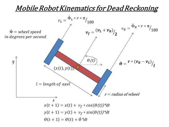
We used dead-reckoning from the encoders and robot kinematics to navigate around the course. The first step for dead reckoning is to keep track of the encoder counts for each wheel using the quadrature of the encoders to either increment or decrement the corresponding count for each rising or falling edge of the encoder signals. At timed intervals, we calculated each wheel's speed based on the number of encoder ticks in that time span. This allowed us to calculate the instantaneous forward velocity of each wheel (which average out to the instantaneous forward velocity of the robot) as well as the instantaneous angular velocity of the robot, as shown in the equations below. By keeping the time-step very short, numerical integration of the forward and angular robot velocities provides a very good estimation of the robot position and orientation over long trials with lots of events. Even if the robot does not reach it's target perfectly after one drive command, the dead reckoning takes this into account for the next drive command to avoid the propagation of errors over long runs. The main issue with this strategy is that it fails if the wheels slip, particularly if they slip on a turn.
The hopper, located in the back of the robot was elevated with a slight tilt down to the back end, which was 3.5” high, so that a servo-motorized door can just let all of the balls out of the back of the robot over the wall. There were two optical interrupt beams in the hopper, one at the bottom to indicate if any balls are stored, and one at the top to indicate if the hopper was full. The indicator that the hopper was full triggered the robot to transition from the harvesting state to the depositing state, and the indicator of whether or not any balls were stored was used to let the robot know if it should deposit before defending a bin at end of the game.
We included a modular option at the front of the robot where two arms could fold out to guide a wider range of balls towards the foam roller. These fold out via a passive release mechanism as soon as the robot starts to drive at the beginning of the game. However we ultimately did not use these arms as they disrupted the driving of our robot, making it more difficult to turn around and sometimes causing wheel slip that could disrupt the dead-reckoning.
We used dead-reckoning from the encoders and robot kinematics to navigate around the course. The first step for dead reckoning is to keep track of the encoder counts for each wheel using the quadrature of the encoders to either increment or decrement the corresponding count for each rising or falling edge of the encoder signals. At timed intervals, we calculated each wheel's speed based on the number of encoder ticks in that time span. This allowed us to calculate the instantaneous forward velocity of each wheel (which average out to the instantaneous forward velocity of the robot) as well as the instantaneous angular velocity of the robot, as shown in the equations below. By keeping the time-step very short, numerical integration of the forward and angular robot velocities provides a very good estimation of the robot position and orientation over long trials with lots of events. Even if the robot does not reach it's target perfectly after one drive command, the dead reckoning takes this into account for the next drive command to avoid the propagation of errors over long runs. The main issue with this strategy is that it fails if the wheels slip, particularly if they slip on a turn.
After sensing which side of the wall it is on with the beacon sensors, the robot would start the harvesting state by driving a circle around the outside of the arena. If a full circle was completed, the robot would move in a foot towards the center of the arena and start a new circle. If at any point the robot stalled against the wall, it would turn around and start driving a slightly smaller circle in the opposite direction. If the hopper was full (or any of the other specific events shown on the state machine occurred), the software transitions to the “depositing” state.
The robot begins the “depositing” state by driving to the front of the bin it has determined is optimal based upon its dead-reckoned coordinates and the current state of the game. Once on the correct side of the arena it will find the beacon above the bin with the IR sensors on the back of the robot to correct its orientation, and then drive in reverse towards the bin, using the two, slightly offset, beacon sensors to stay aligned. A pair of bump sensor on the back indicate when the robot should open the door to the hopper to deposit the balls. If only one of the bump sensors is triggered, the robot spins about that wheel until the other sensor is triggered as well. We then update the dead reckoning position/orientation to the location of that bin, in case the wheels had slipped at any previous point in the game. The robot then either returns to harvest more balls, defends a bin or two, or tries to get into the territory of another bin depending on the state of the game.
