The Circuits
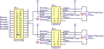
Driving Motor Circuit
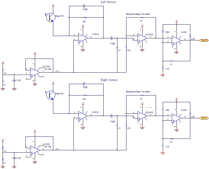
IR Beacon Sensing Circuit
The beacon sensor circuits consist of a rail splitter, a transresistive stage, one gain stage, and a comparator with hysteresis. The gain stage was put in to allow for larger gains if needed, but this proved not to be necessary, so it is operating at a gain of only 1.1. The low pass filter at the transresistive stage has a cutoff frequency of 7.2kHz, much higher than the frequency range of interest. The high pass filter immediately after the transresistive stage has a cutoff frequency of 340Hz. This attenuates the first five harmonics of the signal, and leaves fairly sharp spikes to feed into the comparator input.
The comparator resistors were selected to yield a hysteresis band from 2.32V to 2.48V, in order to maximize our range while preventing noise from triggering the output.
The comparator resistors were selected to yield a hysteresis band from 2.32V to 2.48V, in order to maximize our range while preventing noise from triggering the output.
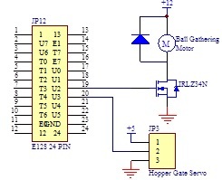
Roller Motor & Depositing Servo Circuit
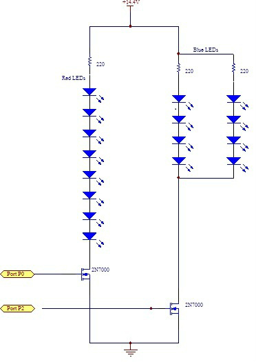
LED Indicator Circuit
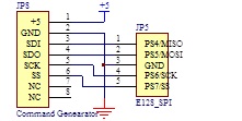
Field Status Reporter (FSR) Pin Connections
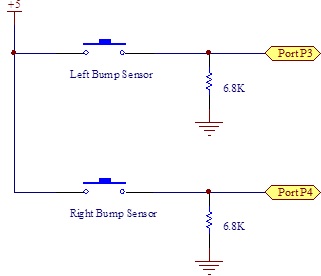
Bump Sensors Circuit
Voltage Regulator Circuits
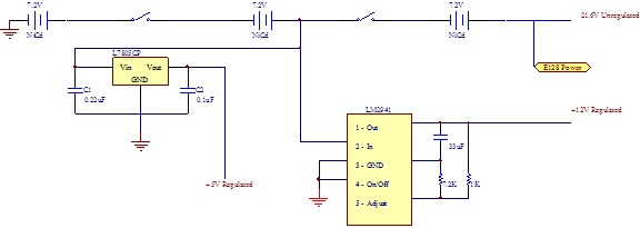
The power distribution board includes two voltage regulators as well as a switch that kills power to the robot. A fixed, linear voltage regulator steps 14.4V down to 5V, which powers all the sensors. A variable, low dropout, linear regulator steps 14.4V down to 12V, which powers the intake roller. The drive motors, E128, and the LEDs are all powered using the unregulated 21.6V.
Downloads
| ball_gathering_motor.pdf |
| beacon_sensing_circuits.pdf |
| field_status_reporter_circuitry.pdf |
| hopper_bump_sensor_circuits.pdf |
| led_indicator_circuit.pdf |
| navigation_motor_driving_circuit.pdf |
| voltage_regulating_circuit.pdf |
